This tutorial is a step-by-step guide that shows you how to build a standalone ESP8266 Web Server that controls two outputs (two LEDs). This ESP8266 Web Server is mobile responsive and it can be accessed with any device that as a browser in your local network.
This tutorial covers two different methods to build the web server:
Part 1: Create a Web Server Using Arduino IDE
Part 2: Create a Web Server Using NodeMCU
PART 1: CREATE A WEB SERVER USING ARDUINO IDE
This part shows you how to create a web server to control two outputs using the Arduino IDE. You can use this method to create a different web server to fulfill your needs.
This tutorial is available in video format (watch below) and in written format (continue reading this page).
Prepare the Arduino IDE
1. Download and install the Arduino IDE on your operating system (some older versions won’t work).
2. Then, you need to install the ESP8266 add-on for the Arduino IDE. For that, go to File > Preferences.
3. Enter http://arduino.esp8266.com/stable/package_esp8266com_index.json into the “Additional Board Manager URLs” field as shown in the figure below. Then, click the “OK” button.
4. Go to Tools > Board > Boards Manager…
5. Scroll down, select the ESP8266 board menu and install “esp8266 platform”, as shown in the figure below.
6. Go to Tools > Board and choose your ESP8266 board. Then, re-open your Arduino IDE.
Code
Copy the code below to your Arduino IDE, but don’t upload it yet. You need to make some changes to make it work for you.
/*********
  Rui Santos
  Complete project details at http://randomnerdtutorials.com
*********/

// Load Wi-Fi library
#include <ESP8266WiFi.h>

// Replace with your network credentials
const char* ssid     = "REPLACE_WITH_YOUR_SSID";
const char* password = "REPLACE_WITH_YOUR_PASSWORD";

// Set web server port number to 80
WiFiServer server(80);

// Variable to store the HTTP request
String header;

// Auxiliar variables to store the current output state
String output5State = "off";
String output4State = "off";

// Assign output variables to GPIO pins
const int output5 = 5;
const int output4 = 4;

void setup() {
  Serial.begin(115200);
  // Initialize the output variables as outputs
  pinMode(output5, OUTPUT);
  pinMode(output4, OUTPUT);
  // Set outputs to LOW
  digitalWrite(output5, LOW);
  digitalWrite(output4, LOW);

  // Connect to Wi-Fi network with SSID and password
  Serial.print("Connecting to ");
  Serial.println(ssid);
  WiFi.begin(ssid, password);
  while (WiFi.status() != WL_CONNECTED) {
    delay(500);
    Serial.print(".");
  }
  // Print local IP address and start web server
  Serial.println("");
  Serial.println("WiFi connected.");
  Serial.println("IP address: ");
  Serial.println(WiFi.localIP());
  server.begin();
}

void loop(){
  WiFiClient client = server.available();   // Listen for incoming clients

  if (client) {                             // If a new client connects,
    Serial.println("New Client.");          // print a message out in the serial port
    String currentLine = "";                // make a String to hold incoming data from the client
    while (client.connected()) {            // loop while the client's connected
      if (client.available()) {             // if there's bytes to read from the client,
        char c = client.read();             // read a byte, then
        Serial.write(c);                    // print it out the serial monitor
        header += c;
        if (c == '\n') {                    // if the byte is a newline character
          // if the current line is blank, you got two newline characters in a row.
          // that's the end of the client HTTP request, so send a response:
          if (currentLine.length() == 0) {
            // HTTP headers always start with a response code (e.g. HTTP/1.1 200 OK)
            // and a content-type so the client knows what's coming, then a blank line:
            client.println("HTTP/1.1 200 OK");
            client.println("Content-type:text/html");
            client.println("Connection: close");
            client.println();

            // turns the GPIOs on and off
            if (header.indexOf("GET /5/on") >= 0) {
              Serial.println("GPIO 5 on");
              output5State = "on";
              digitalWrite(output5, HIGH);
            } else if (header.indexOf("GET /5/off") >= 0) {
              Serial.println("GPIO 5 off");
              output5State = "off";
              digitalWrite(output5, LOW);
            } else if (header.indexOf("GET /4/on") >= 0) {
              Serial.println("GPIO 4 on");
              output4State = "on";
              digitalWrite(output4, HIGH);
            } else if (header.indexOf("GET /4/off") >= 0) {
              Serial.println("GPIO 4 off");
              output4State = "off";
              digitalWrite(output4, LOW);
            }

            // Display the HTML web page
            client.println("<!DOCTYPE html><html>");
            client.println("<head><meta name=\"viewport\" content=\"width=device-width, initial-scale=1\">");
            client.println("<link rel=\"icon\" href=\"data:,\">");
            // CSS to style the on/off buttons
            // Feel free to change the background-color and font-size attributes to fit your preferences
            client.println("<style>html { font-family: Helvetica; display: inline-block; margin: 0px auto; text-align: center;}");
            client.println(".button { background-color: #195B6A; border: none; color: white; padding: 16px 40px;");
            client.println("text-decoration: none; font-size: 30px; margin: 2px; cursor: pointer;}");
            client.println(".button2 {background-color: #77878A;}</style></head>");

            // Web Page Heading
            client.println("<body><h1>ESP8266 Web Server</h1>");

            // Display current state, and ON/OFF buttons for GPIO 5
            client.println("<p>GPIO 5 - State " + output5State + "</p>");
            // If the output5State is off, it displays the ON button
            if (output5State=="off") {
              client.println("<p><a href=\"/5/on\"><button class=\"button\">ON</button></a></p>");
            } else {
              client.println("<p><a href=\"/5/off\"><button class=\"button button2\">OFF</button></a></p>");
            }

            // Display current state, and ON/OFF buttons for GPIO 4
            client.println("<p>GPIO 4 - State " + output4State + "</p>");
            // If the output4State is off, it displays the ON button
            if (output4State=="off") {
              client.println("<p><a href=\"/4/on\"><button class=\"button\">ON</button></a></p>");
            } else {
              client.println("<p><a href=\"/4/off\"><button class=\"button button2\">OFF</button></a></p>");
            }
            client.println("</body></html>");

            // The HTTP response ends with another blank line
            client.println();
            // Break out of the while loop
            break;
          } else { // if you got a newline, then clear currentLine
            currentLine = "";
          }
        } else if (c != '\r') {  // if you got anything else but a carriage return character,
          currentLine += c;      // add it to the end of the currentLine
        }
      }
    }
    // Clear the header variable
    header = "";
    // Close the connection
    client.stop();
    Serial.println("Client disconnected.");
    Serial.println("");
  }
}
You need to modify the following two variables with your network credentials, so that your ESP8266 can establish a connection with your router.
// Replace with your network credentials
 const char* ssid = "";
 const char* password = "";
Uploading the Sketch
Uploading the Sketch to the ESP-12E
If you’re using an ESP-12E NodeMCU Kit, uploading the sketch is very simple, since it has built-in programmer. Plug your board to your computer. Make sure you have the right board and COM port selected.
Then, click the “Upload Button” in the Arduino IDE and wait a few seconds until you see the message “Done uploading.” in the bottom left corner.
Uploading Sketch to the ESP-01
Uploading code to the ESP-01 requires establishing a serial communication between your ESP8266 and a FTDI Programmer as shown in the schematic diagram below.
The following table shows the connections you need to make between the ESP8266 and the FTDI programmer.
ESP8266
FTDI programmer
RX
TX
TX
RX
CH_PD
3.3V
GPIO 0
GND
VCC
3.3V
GND
GND
If you have a brand new FTDI Programmer and you need to install your FTDI drivers on Windows PC, visit this website for the official drivers. Alternatively, you can contact
the seller that sold you the FTDI Programmer.
Then, you just need to connect the FTDI programmer to your computer, and upload the code to the ESP8266.
Schematics
To build the circuit you need the following parts:
You can use the preceding links or go directly to MakerAdvisor.com/tools to find all the parts for your projects at the best price!
Connect two LEDs to your ESP8266 as shown in the following schematic diagram – with one LED connected to GPIO 4, and another to GPIO 5.
If you are using ESP-01…
If you’re using the ESP8266-01, use the following schematic diagram as a reference, but you need change the GPIOs assignment in the code (to GPIO 2 and GPIO 0).
Testing the Web Server
Now, you can upload the code, and it will work straight away. Don’t forget to check if you have the right board and COM port selected, otherwise you’ll get an error when trying to upload. Open the Serial Monitor at a baud rate of 115200.
Finding the ESP IP Address
Press the ESP8266 RESET button, and it will output the ESP IP address on the Serial Monitor
Copy that IP address, because you need it to access the web server.
Accessing the Web Server
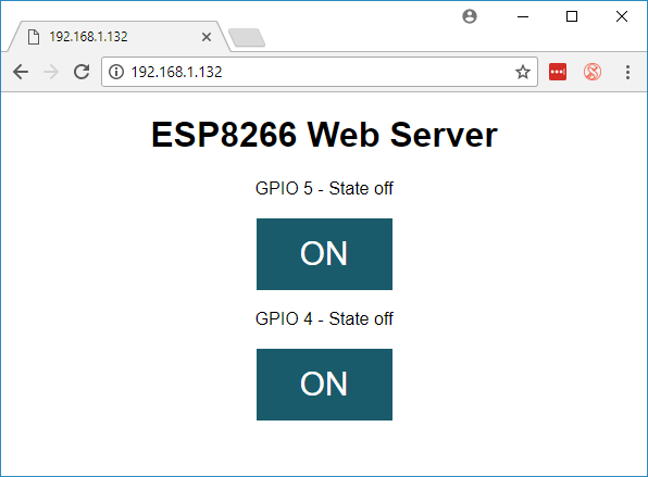
Open your browser, type the ESP IP address, and you’ll see the following page. This page is sent by the ESP8266 when you make a request on the ESP IP address.
If take a look at the serial monitor, you can see what’s going on on the background. The ESP receives an HTTP request from a new client – in this case, your browser.
You can also see other information about the HTTP request – these fields are called HTTP header fields, and they define the operating parameters of an HTTP transaction.
Testing the Web Server
Let’s test the web server. Click the button to turn GPIO 5 ON. The ESP receives a request on the /5/on URL, and turns LED 5 ON.
The LED state is also updated on the web page.
Test GPIO 4 button and check that it works in a similar way.
How the Code Works
Now, let’s take a closer look at the code to see how it works, so that you are able to modify it to fulfill your needs.
The first thing you need to do is to include the ESP8266WiFi library.
// Load Wi-Fi library
#include <ESP8266WiFi.h>
As mentioned previously, you need to insert your ssid and password in the following lines inside the double quotes.
const char* ssid = "";
const char* password = "";
Then, you set your web server to port 80.
// Set web server port number to 80
WiFiServer server(80);
The following line creates a variable to store the header of the HTTP request:
String header;
Next, you create auxiliar variables to store the current state of your outputs. If you want to add more outputs and save its state, you need to create more variables.
// Auxiliar variables to store the current output state
String output5State = "off";
String output4State = "off";
You also need to assign a GPIO to each of your outputs. Here we are using GPIO 5 and GPIO 4. You can use any other suitable GPIOs.
// Assign output variables to GPIO pins
const int output5 = 5;
const int output4 = 4;
setup()
Now, let’s go into the setup(). The setup() function only runs once when your ESP first boots. First, we start a serial communication at a baud rate of 115200 for debugging purposes.
Serial.begin(115200);
You also define your GPIOs as OUTPUTs and set them to LOW.
// Initialize the output variables as outputs
pinMode(output5, OUTPUT);
pinMode(output4, OUTPUT);
// Set outputs to LOW
digitalWrite(output5, LOW);
digitalWrite(output4, LOW);
The following lines begin the Wi-Fi connection with WiFi.begin(ssid, password), wait for a successful connection and prints the ESP IP address in the Serial Monitor.
// Connect to Wi-Fi network with SSID and password
Serial.print("Connecting to ");
Serial.println(ssid);
WiFi.begin(ssid, password);
while (WiFi.status() != WL_CONNECTED) {
 delay(500);
 Serial.print(".");
}
// Print local IP address and start web server
Serial.println("");
Serial.println("WiFi connected.");
Serial.println("IP address: ");
Serial.println(WiFi.localIP());
server.begin();
loop()
In the loop() we program what happens when a new client establishes a connection with the web server.
The ESP is always listening for incoming clients with this line:
WiFiClient client = server.available(); // Listen for incoming clients
When a request is received from a client, we’ll save the incoming data. The while loop that follows will be running as long as the client stays connected. We don’t recommend changing the following part of the code unless you know exactly what you are doing.
if (client) { // If a new client connects,
 Serial.println("New Client."); // print a message out in the serial port
 String currentLine = ""; // make a String to hold incoming data from the client
 while (client.connected()) { // loop while the client's connected
 if (client.available()) { // if there's bytes to read from the client,
 char c = client.read(); // read a byte, then
 Serial.write(c); // print it out the serial monitor
 header += c;
 if (c == '\n') { // if the byte is a newline character
 // if the current line is blank, you got two newline characters in a row.
 // that's the end of the client HTTP request, so send a response:
 if (currentLine.length() == 0) {
 // HTTP headers always start with a response code (e.g. HTTP/1.1 200 OK)
 // and a content-type so the client knows what's coming, then a blank line:
 client.println("HTTP/1.1 200 OK");
 client.println("Content-type:text/html");
 client.println("Connection: close");
 client.println();
The next section of if and else statements checks which button was pressed in your web page, and controls the outputs accordingly. As we’ve seen previously, we make a request on different URLs depending on the button we press.
// turns the GPIOs on and off
if (header.indexOf("GET /5/on") >= 0) {
 Serial.println("GPIO 5 on");
 output5State = "on";
 digitalWrite(output5, HIGH);
} else if (header.indexOf("GET /5/off") >= 0) {
 Serial.println("GPIO 5 off");
 output5State = "off";
 digitalWrite(output5, LOW);
} else if (header.indexOf("GET /4/on") >= 0) {
 Serial.println("GPIO 4 on");
 output4State = "on";
 digitalWrite(output4, HIGH);
} else if (header.indexOf("GET /4/off") >= 0) {
 Serial.println("GPIO 4 off");
 output4State = "off";
 digitalWrite(output4, LOW);
}
For example, if you’ve pressed the GPIO 5 ON button, the URL changes to the ESP IP address followed by /5/ON, and we receive that information on the HTTP header. So, we can check if the header contains the expression GET /5/on.
If it contains, the code prints a message on the serial monitor, changes the output5Statevariable to on, and turns the LED on.
This works similarly for the other buttons. So, if you want to add more outputs, you should modify this part of the code to include them.
Displaying the HTML Web Page
The next thing you need to do, is generate the web page. The ESP will be sending a response to your browser with some HTML text to display the web page.
The web page is sent to the client using the client.println() function. You should enter what you want to send to the client as an argument.
The first text you should always send is the following line, that indicates that we’re sending HTML.
<!DOCTYPE html><html>
Then, the following line makes the web page responsive in any web browser.
Next, we have some CSS to style the buttons and the web page appearance. We choose the Helvetica font, define the content to be displayed as a block and aligned at the center.
Then, we define the style for a second button, with all the properties of the button we’ve defined earlier, but with a different color. This will be the style for the off button.
In the next line you set the first heading of your web page, you can change this text to whatever you like.
// Web Page Title
client.println("<h1>ESP8266 Web Server</h1>");
Displaying the Buttons and Corresponding State
Then, you write a paragraph to display the GPIO 5 current state. As you can see we use the output5State variable, so that the state updates instantly when this variable changes.
client.println("<p>GPIO 5 - State " + output5State + "</p>");
Then, we display the on or the off button, depending on the current state of the GPIO.
Finally, when the response ends, we clear the header variable, and stop the connection with the client with client.stop().
// Clear the header variable
header = "";
// Close the connection
client.stop();
Taking it Further
Now that you know how the code works, you can modify the code to add more outputs, or modify your web page. To modify your web page you may need to know some HTML and CSS basics. Instead of controlling two LEDs, you can control a relay to control practically any electronics appliances.
If you like ESP8266 make sure you check our course about Home Automation with the ESP8266. Also, make sure you check our most popular projects at the bottom of the post.
PART 2: CREATE A WEB SERVER USING NODEMCU
This part shows you how to create a web server to control two outputs using NodeMCU firmware and LUA programming language. You can use this method to create a different web server to fulfill your needs.
First, watch the video demonstration below
Why flashing your ESP8266 module with NodeMCU?
NodeMCU is a firmware that allows you to program the ESP8266 modules with LUA script. Programming the ESP8266 with LUA using the NodeMCU firmware is very similar to the way you program your Arduino. With just a few lines of code you can establish a WiFi connection, control the ESP8266 GPIOs, turning your ESP8266 into a web server and a lot more.
Downloading NodeMCU Flasher for Windows
After wiring your circuit, you have to download the NodeMCU flasher. It’s a .exe file that you can download using one of the following links:
You can click here to find all the information about NodeMCU flasher.
Flashing your ESP8266
If you’re using an ESP8266-12 you just need to plug the ESP into your computer. If you’re using an ESP-01, you need an FTDI programmer to connect it to your computer. To establish a serial communication between your ESP8266 and a FTDI Programmer as shown in the schematic diagram below.
Open the flasher that you just downloaded and a window should appear (as shown in the following figure).
Press the button “Flash” and it should start the flashing process immediately (You might have to change some of the settings on the Advanced tab). After finishing this process, it should appear a green circle with a check icon.
Schematics
To build the circuit you need the following parts:
You can use the preceding links or go directly to MakerAdvisor.com/tools to find all the parts for your projects at the best price!
If your using ESP-01…
If you’re using the ESP8266-01, use the following schematic diagram as a reference.
Uploading the Code
I recommend using the ESPlorer program created by 4refr0nt to create and save LUA files into your ESP8266. Follow these instructions to download and install ESPlorer:
Go to the dist folder (here’s the path: ESPlorer-master\ESPlorer\dist)
Run ESPlorer.jar. It’s a JAVA program, so you need JAVA installed on your computer.
Open the ESPlorer
You should see a window similar to the preceding Figure, follow these instructions to upload a LUA file:
Connect your FTDI programmer to your computer
Select your FTDI programmer port
Press Open/Close
Select NodeMCU+MicroPtyhon tab
Create a new file called init.lua
Press Save to ESP
Everything that you need to worry about or change is highlighted in red box.
Code
Upload the following code into your ESP8266 using the preceding software. Your file should be named “init.lua“. You can click here to download the file.
wifi.setmode(wifi.STATION)
wifi.sta.config("YOUR_NETWORK_NAME","YOUR_NETWORK_PASSWORD")
print(wifi.sta.getip())
led1 = 3
led2 = 4
gpio.mode(led1, gpio.OUTPUT)
gpio.mode(led2, gpio.OUTPUT)
srv=net.createServer(net.TCP)
srv:listen(80,function(conn)
conn:on("receive", function(client,request)
local buf = "";
local _, _, method, path, vars = string.find(request, "([A-Z]+) (.+)?(.+) HTTP");
if(method == nil)then
_, _, method, path = string.find(request, "([A-Z]+) (.+) HTTP");
end
local _GET = {}
if (vars ~= nil)then
for k, v in string.gmatch(vars, "(%w+)=(%w+)&*") do
_GET[k] = v
end
end
buf = buf.."<h1> ESP8266 Web Server</h1>";
buf = buf.."<p>GPIO0 <a href=\"?pin=ON1\"><button>ON</button></a> <a href=\"?pin=OFF1\"><button>OFF</button></a></p>";
buf = buf.."<p>GPIO2 <a href=\"?pin=ON2\"><button>ON</button></a> <a href=\"?pin=OFF2\"><button>OFF</button></a></p>";
local _on,_off = "",""
if(_GET.pin == "ON1")then
gpio.write(led1, gpio.HIGH);
elseif(_GET.pin == "OFF1")then
gpio.write(led1, gpio.LOW);
elseif(_GET.pin == "ON2")then
gpio.write(led2, gpio.HIGH);
elseif(_GET.pin == "OFF2")then
gpio.write(led2, gpio.LOW);
end
client:send(buf);
client:close();
collectgarbage();
end)
end)
Don’t forget to replace your WiFi Station details in that code above (Network Name and Password).
Accessing your web server
When your ESP8266 restarts it prints in your serial monitor the IP address of your ESP8266. If you type your ESP8266 IP address in your web browser, you can access your web server.