


| https://www.eprojectszone.com/how-to-modify-the-pwm-frequency-on-the-arduino-part1/ | |
How to modify the PWM frequency on the arduino-part1(fast PWM and Timer 0)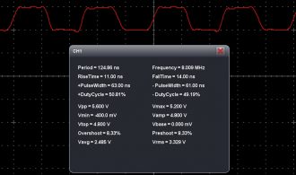
The default frequency of arduino PWM pins is around 490Hz for 9, 10, 3,11 and around 980 HZ for 5, 6, but for many applications we need some higher frequencies. The arduino uno can generate frequencies for PWM pins up to 8Mhz. To modify these values we need to work with timers(which contains registers). For PWM, arduino has three timers one for two pins like: -timer 0- for pins 5 and 6 -timer 1-for pins 9 and 10 -timer 2-for pins 3 and 11 Beside these registers arduino can put the PWM pin in four modes like -fast PWM -phase correct pwm -frequency and phase correct pwm -ctc mode Before to talk about timers let’s have a look at these PWM modes because we choose them from the timers bits: Fast PWM mode -timer count from a BOTTOM value to a TOP value after that it overflow to BOTTOM value and repeat(sawtooth waveform), it can generate higher frequencies(picture from atmega datasheet).
For this mode the possible frequencies are given by the formula f=f_clk/N*256, where f is the neccesary frequency, f_clk is the oscillator frequency(16Mhz) and N is the prescaler(it has precise values and it is given form the timer’s bits so we will explain it in more details when we will talk about timers). Phase correct PWM mode-timer count from a BOTTOM value to a TOP value after that it not overflow it countdown from TOP value to BOTTOM value and repeat(triangle wave). This mode has half of fast pwm mode frequency.It is preferred in motors control(picture from atmega datasheet).
For this mode the possible frequencies are given by the formula f=f_clk/N*510, with all the variables like in the fast pwm mode. Frequency and phase correct pwm(only on timer 1)-are the same with phase correct pwm if the TOP value remains the same, if not let asumme that we have two TOP values TOP1 and TOP2, TOP1>TOP 2, when the timer count up to TOP 1 and down to BOTTOM the pulse have a specific time period but when the timer count up to TOP 2 and down to BOTTOM, because the TOP 2 is smaller than TOP 1 the pulse have a small time period so a higher frequency(picture from atmega datasheet).
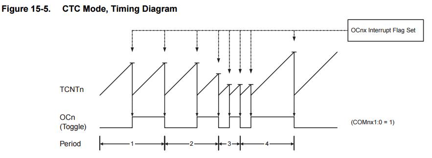
CTC mode-in this mode timer count to a TOP value and when it reach that value clear the timer and execute something. This mode let us to make very precise operation(picture from atmega datasheet).
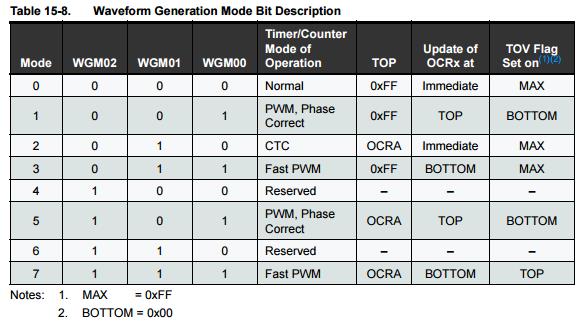
Now let’s talk about timers! Timer 0 manage pins 5 and 6, so next in a couple of examples we will show you how to manage the pwm frequencies. Let’s assume we want to generate a Fast PWM Mode with a duty cycle at 50% (we will explain when we reach at the OCRA register ). To choose the fast pwm mode in the TCCR0A we must make the WGM01 and WGM00 bits equals 1 like in the pictures below(from atmega datasheet).
As we explained in this article in the arduino program we have TCCR0A=B10100011; this means that the WGM00 and WGM01 from the TCCR0A register are 1 which means that the pins 5 and 6 are in the fast pwm mode.
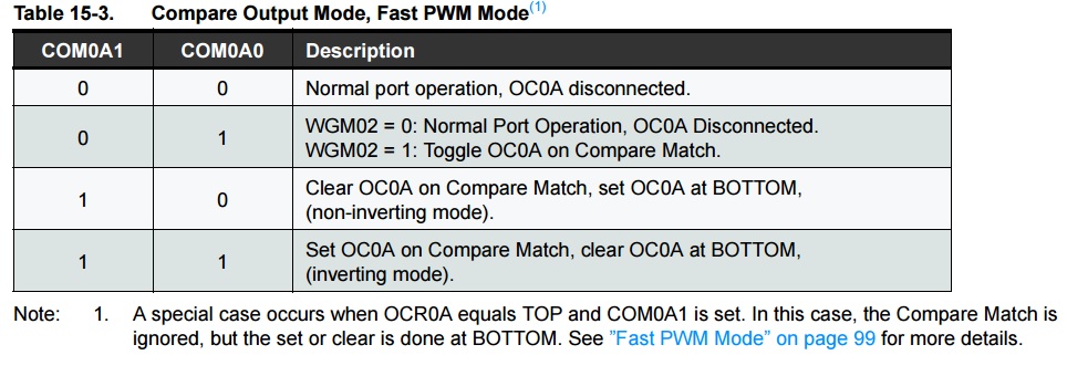
But first bit and the third why are they 1??? These bits are COM0A1 and COM0B1 and in the images below you(from atmega datasheet) can see that they controls the pin 6(COM0A1) and 5(COM0B1).
If we choose all bits(COM0A1 COM0A0,COM0B 1and COM0B0) 0 the pins are disconnected(they don’t work). If you choose the COM0A1, COM0B1 1 and COM0A0, COM0B0 0 then pins 5 and 6 generate a PWM and with a prescaler let’s say 64(explain soon) from the formula f=f_clk/N*256 we will have a 976 Hz pwm signal. In the image below we have such a signal(976.6Hz and a 20% duty cycle(ON) and 80%(OFF) (50 in program because it is from 0 to 255))
The program for this signal is: void setup() { If you choose all COM0A1, COM0B1 and COM0A0, COM0B0 1 then pins 5 and 6 generate a PWM and with a prescaler let’s say 64(explain soon) from the formula f=f_clk/N*256 we will have a 976 Hz pwm signal, but this signal is inverted like in the picture below so duty cycle is 80% (ON) and 20% (OFF):
The program for this signal is: void setup() {
Now if you choose COM0A1 0 and COM0A0 1 and make the WGM02 bit from TCCR0B register 1, the pin 5 is disconnected and timer counts for pin 6 until it’s reach OCR0A not until 255(if OCR0A is not 255) which is maximum. Ok ok but what is the relation between OCR0A and frequency. Also from datasheet we have the formula (it is in CTC mode but it is avaible in here also) fOCR0A=fclk/2*N*(1+OCR0A). With these setting you can obtain up to 8Mhz 50%(fixed) duty cycle signal (if OCRA is 0 and we have no prescaler) but only on pin 6 like in the picture below:
This mode has advantage that can reach very high frequencies but the disavantage is that you have a fix duty cycle. The program to reach 8Mhz is: void setup() { If OCR0A is 50(and no prescaler) the frequency from formula is 156.862Hz as you can see in the image from oscilloscope:
The program is: void setup() { With the formula OCR0A =(fclk/2*N*fOCR0A) -1 (first formula but rearranged) and this mode if you want a specified frequency you calculate the OCR0A and introduce it in the program. For example if you want a 25kHz (but is at 50% duty cycle) you must choose a OCR0A=39 and a prescaler=8, because if we don’t use prescaler the OCR0A from the formula give us OCR0A=319, and because timer 0 has 8bits the OCR0A <= 255. The result is:
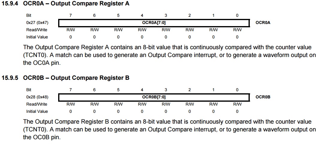
And the program: void setup() { Finally we will talk about prescaler, OCR0A and OCR0B(which give the duty cycle). The prescaler is used to control the frequency(from formules) and is managed in the TCCR0B register like in the images(from atmega datasheet)
It is controlled by CS00, CS01 and CS02 bits with different combinations as you can see in the image above. Now the OCR0A and OCR0B registers can take values from 0 to 255 because they are on 8 bits(they can be written on decimals-as we do) and OCR0A How to modify the PWM frequency on the arduino-part1(fast PWM and Timer 0)Please let us in the comment zone any suggestions that you think will improve the article! If you like the article click the follow button from social media to stay in touch with us!
The default frequency of arduino PWM pins is around 490Hz for 9, 10, 3,11 and around 980 HZ for 5, 6, but for many applications we need some higher frequencies. The arduino uno can generate frequencies for PWM pins up to 8Mhz. To modify these values we need to work with timers(which contains registers). For PWM, arduino has three timers one for two pins like: -timer 0- for pins 5 and 6 -timer 1-for pins 9 and 10 -timer 2-for pins 3 and 11 Beside these registers arduino can put the PWM pin in four modes like -fast PWM -phase correct pwm -frequency and phase correct pwm -ctc mode Before to talk about timers let’s have a look at these PWM modes because we choose them from the timers bits: Fast PWM mode -timer count from a BOTTOM value to a TOP value after that it overflow to BOTTOM value and repeat(sawtooth waveform), it can generate higher frequencies(picture from atmega datasheet).
For this mode the possible frequencies are given by the formula f=f_clk/N*256, where f is the neccesary frequency, f_clk is the oscillator frequency(16Mhz) and N is the prescaler(it has precise values and it is given form the timer’s bits so we will explain it in more details when we will talk about timers). Phase correct PWM mode-timer count from a BOTTOM value to a TOP value after that it not overflow it countdown from TOP value to BOTTOM value and repeat(triangle wave). This mode has half of fast pwm mode frequency.It is preferred in motors control(picture from atmega datasheet).
For this mode the possible frequencies are given by the formula f=f_clk/N*510, with all the variables like in the fast pwm mode. Frequency and phase correct pwm(only on timer 1)-are the same with phase correct pwm if the TOP value remains the same, if not let asumme that we have two TOP values TOP1 and TOP2, TOP1>TOP 2, when the timer count up to TOP 1 and down to BOTTOM the pulse have a specific time period but when the timer count up to TOP 2 and down to BOTTOM, because the TOP 2 is smaller than TOP 1 the pulse have a small time period so a higher frequency(picture from atmega datasheet).
CTC mode-in this mode timer count to a TOP value and when it reach that value clear the timer and execute something. This mode let us to make very precise operation(picture from atmega datasheet).
Now let’s talk about timers! Timer 0 manage pins 5 and 6, so next in a couple of examples we will show you how to manage the pwm frequencies. Let’s assume we want to generate a Fast PWM Mode with a duty cycle at 50% (we will explain when we reach at the OCRA register ). To choose the fast pwm mode in the TCCR0A we must make the WGM01 and WGM00 bits equals 1 like in the pictures below(from atmega datasheet).
As we explained in this article in the arduino program we have TCCR0A=B10100011; this means that the WGM00 and WGM01 from the TCCR0A register are 1 which means that the pins 5 and 6 are in the fast pwm mode.
But first bit and the third why are they 1??? These bits are COM0A1 and COM0B1 and in the images below you(from atmega datasheet) can see that they controls the pin 6(COM0A1) and 5(COM0B1).
If we choose all bits(COM0A1 COM0A0,COM0B 1and COM0B0) 0 the pins are disconnected(they don’t work). If you choose the COM0A1, COM0B1 1 and COM0A0, COM0B0 0 then pins 5 and 6 generate a PWM and with a prescaler let’s say 64(explain soon) from the formula f=f_clk/N*256 we will have a 976 Hz pwm signal. In the image below we have such a signal(976.6Hz and a 20% duty cycle(ON) and 80%(OFF) (50 in program because it is from 0 to 255))
The program for this signal is: void setup() { If you choose all COM0A1, COM0B1 and COM0A0, COM0B0 1 then pins 5 and 6 generate a PWM and with a prescaler let’s say 64(explain soon) from the formula f=f_clk/N*256 we will have a 976 Hz pwm signal, but this signal is inverted like in the picture below so duty cycle is 80% (ON) and 20% (OFF):
The program for this signal is: void setup() {
Now if you choose COM0A1 0 and COM0A0 1 and make the WGM02 bit from TCCR0B register 1, the pin 5 is disconnected and timer counts for pin 6 until it’s reach OCR0A not until 255(if OCR0A is not 255) which is maximum. Ok ok but what is the relation between OCR0A and frequency. Also from datasheet we have the formula (it is in CTC mode but it is avaible in here also) fOCR0A=fclk/2*N*(1+OCR0A). With these setting you can obtain up to 8Mhz 50%(fixed) duty cycle signal (if OCRA is 0 and we have no prescaler) but only on pin 6 like in the picture below:
This mode has advantage that can reach very high frequencies but the disavantage is that you have a fix duty cycle. The program to reach 8Mhz is: void setup() { If OCR0A is 50(and no prescaler) the frequency from formula is 156.862Hz as you can see in the image from oscilloscope:
The program is: void setup() { With the formula OCR0A =(fclk/2*N*fOCR0A) -1 (first formula but rearranged) and this mode if you want a specified frequency you calculate the OCR0A and introduce it in the program. For example if you want a 25kHz (but is at 50% duty cycle) you must choose a OCR0A=39 and a prescaler=8, because if we don’t use prescaler the OCR0A from the formula give us OCR0A=319, and because timer 0 has 8bits the OCR0A <= 255. The result is:
And the program: void setup() { Finally we will talk about prescaler, OCR0A and OCR0B(which give the duty cycle). The prescaler is used to control the frequency(from formules) and is managed in the TCCR0B register like in the images(from atmega datasheet)
It is controlled by CS00, CS01 and CS02 bits with different combinations as you can see in the image above. Now the OCR0A and OCR0B registers can take values from 0 to 255 because they are on 8 bits(they can be written on decimals-as we do) and OCR0A is for pin 6 and OCR0B is for pin 5 like in the image below:
is for pin 6 and OCR0B is for pin 5 like in the image below:
|
|